

Hydraulic Rotary Union Manufacturer Essentials for High-Pressure Applications
2026-09-12
When a hydraulic system pushes past 5,000 psi, even a small leak in a rotary union can shut down an entire operation. Yet many engineers still treat these components as an afterthought—until a seal fails or a shaft seizes. If you’re sourcing a rotary union for high-pressure service, the difference between a reliable manufacturer and a costly mistake often comes down to details you won’t find on a generic datasheet. MOFLON has spent years refining those details for demanding applications. This guide breaks down what actually matters when evaluating a hydraulic rotary union manufacturer for high-pressure environments—so you can avoid the common traps and specify with confidence.
Why High-Pressure Hydraulic Rotary Unions Fail Before Their Rated Life
Most premature failures in high-pressure hydraulic rotary unions trace back to pressure fluctuations that never appear on a static datasheet. Rated life assumes a steady supply pressure, but real circuits generate sharp spikes during valve shifts, load reversals, and pump ripple. Each spike forces the sealing faces apart just enough to let a micro-film of fluid escape, then slams them back together. Over thousands of cycles this hammering erodes the lapped surfaces, widens the internal clearance, and eventually causes a blow-by that looks sudden but has actually been building for months.
Another overlooked factor is the interaction between shaft misalignment and internal pressure. Under high pressure, the rotary union's housing deflects slightly, changing the contact patch of the seals. If the shaft is even a few thousandths off axis, that deflection becomes uneven, concentrating wear on one side. Dirt and varnish from oxidized oil then embed in the softer seal material, turning it into a fine abrasive lap. The damage accelerates once the balance ratio shifts, because a worn seal behaves differently than a new one, and the original safety margin quietly disappears well before the rated hours are reached.
Seal Groove Design and Surface Finish That Hold Back Pressure Spikes
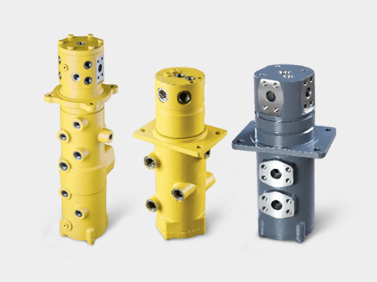
Groove geometry often gets overlooked until a spike pushes the seal toward the clearance gap. A shallow, well-supported cavity with a radius at the bottom corners keeps the elastomer from extruding under sudden load. If the sidewalls are even slightly tapered or the bottom surface shows chatter marks, pressure can wedge the seal into a pinch point and start a tear long before rated limits are reached.
Surface finish works hand in hand with that geometry. On the dynamic sealing surface, a finish in the Ra 0.2 to 0.4 μm range holds enough lubricant to prevent stick-slip while still being smooth enough to avoid abrading the seal lip. Static groove floors need the same attention: a polished but not mirror-like texture prevents the seal from gripping too hard and reduces localized stress when a pressure wave hits.
When spikes are expected, adding a back-up ring is common, but it rarely fixes a groove that is too wide or has sharp entry edges. A small chamfer at the low-pressure side allows the seal to move progressively instead of snapping against the corner. Likewise, isotropic surface lay on the rod or bore—rather than a directional grind pattern—helps distribute contact pressure more evenly as the seal flexes under transient loads.
Bearing Selection for Combined Radial, Axial, and Moment Loads
When a bearing must handle radial and axial forces together with a tilting moment, the selection process moves well beyond basic load ratings. The first step is to break down the applied loads at the bearing location, resolving the moment into an equivalent force couple. This often reveals that a single row angular contact or deep groove bearing is insufficient, pushing the design toward paired arrangements or specialized designs like crossed roller or slewing bearings.
A practical approach involves calculating the equivalent dynamic load using the ratio of axial to radial force, then checking the resulting load against the bearing's static and dynamic capacity. However, moment loads create uneven internal stress distributions, so it is wise to consult manufacturer curves that show permissible tilting angles or combined load diagrams. Ignoring the moment component frequently leads to premature cage failure or edge loading on the raceways, even when the basic load ratings appear adequate.
For applications with substantial moment, such as robot joints or crane hooks, designers often opt for a four-point contact ball bearing or a pair of tapered roller bearings mounted face-to-face. These configurations provide inherent resistance to overturning while keeping axial play low. A useful rule is to verify that the applied moment does not exceed roughly twenty percent of the product of the bearing's axial capacity and its pitch diameter, though actual limits vary by series and preload.
Flow Path Geometry and Its Effect on Heat Buildup at Full Pressure
The shape of internal flow channels directly affects how much heat accumulates when a system runs at full pressure. Tight bends, abrupt cross-section changes, and dead-end cavities force the fluid to deviate sharply, creating local pressure drops and zones of recirculation. At full pressure, the higher fluid density and velocity amplify frictional heating along walls, and any geometric discontinuity becomes a spot where kinetic energy is converted into thermal energy rather than being carried downstream.
One often overlooked aspect is that flow path geometry controls residence time. A longer, convoluted path gives the fluid more contact with hot surfaces and more opportunities for viscous dissipation. In contrast, a flow path designed with large radii, gradual tapers, and minimal surface roughness reduces turbulence intensity and shear stress, so less mechanical energy turns into heat. When the system operates at full pressure, even small improvements in corner rounding or port alignment can shift the local temperature distribution enough to avoid hot spots near seals or sensors.
Because full-pressure operation skews the energy balance, designers should treat geometry as a thermal management tool. For example, replacing a sharp 90-degree elbow with a swept bend may lower the peak wall temperature by several degrees. Similarly, eliminating sudden expansions that cause jet separation prevents low-velocity pockets from trapping heated fluid. These geometry-driven adjustments matter most when the fluid is compressible or when pressure-dependent viscosity changes make local flow acceleration more sensitive to channel contours.
Material Pairing for Wear Resistance in Contaminated Hydraulic Fluid
Contaminated hydraulic fluid carries abrasive particles that act like a lapping compound between moving surfaces. When two materials rub together under load, the pairing of their hardness, microstructure, and surface finish determines whether wear stays mild or accelerates into failure. A common oversight is matching identical hardness levels on both sides of the contact—this can actually promote particle embedding and transfer, while a deliberate mismatch often cuts wear rates in half.
For sliding pairs exposed to silica or metal debris, a hard coating on one component paired with a tougher, slightly softer counterface tends to perform best. The hard surface resists scoring and breaks down incoming particles, while the softer material yields just enough to trap fragments away from the contact zone. Examples include tungsten carbide against nitrided steel, or ceramic-coated pistons running in hardened cast iron bores. These combinations rely on differential hardness rather than absolute hardness, and they tolerate occasional overloads without catastrophic galling.
Field data from injection molding machines and off-highway equipment shows that a hardness ratio between 1.3 and 1.8 on the Mohs or Vickers scale dramatically reduces three-body abrasive wear. Too little difference lets particles roll and indent both surfaces; too much can cause the harder side to plough grooves into the softer one. Surface texture also matters—polishing the hard member to below 0.1 µm Ra while leaving the soft side with a fine crosshatch pattern provides micro-reservoirs for debris and boundary lubricant, effectively extending service intervals even with heavily contaminated oil.
Pre-Shipment Pressure Cycling and Leak Testing Worth Paying For
Pre-shipment pressure cycling and leak testing is often treated as an add-on, but it should be the default for any component that holds fluid or gas under changing loads. Static checks miss the slow failures that only appear after repeated expansion and contraction of seals, threads, and welds. Paying for this test before the container leaves means catching a bad batch while it is still cheap to correct, not after it has reached a customer's site.
A proper cycle test pushes the part from low to high pressure and back again, sometimes hundreds of times, until weak points start to show. Leak testing then quantifies the pressure drop instead of relying on a quick bubble check that can pass a part with a pinhole-sized flaw. Suppliers that charge for this service are usually the ones confident enough in their work to put the results in writing. That confidence is worth more than the test itself.
Think of it less as insurance and more as a filter. Insurance pays out after a failure; pressure cycling and leak testing removes the failure before it ships. For buyers who deal with long lead times or remote installations, the extra cost per order is small compared to a single field replacement or a recall. It is a simple question: would you rather find the leak in the factory, or have your customer find it for you?
FAQ
A high-pressure rotary union must handle fluid pressures often exceeding 5,000 psi while maintaining a leak-free rotating seal. Core design factors include balanced mechanical seals, hardened steel or stainless steel housings, and precision-machined bearing surfaces to minimize deflection under load.
Seal materials directly determine the union's pressure and temperature limits. For aggressive hydraulic fluids and extreme pressures, manufacturers often use polyurethane, PTFE compounds, or high-performance elastomers like HNBR. The material must resist extrusion, wear, and chemical breakdown while maintaining low friction during continuous rotation.
Premium high-pressure rotary unions are machined to tolerances within a few microns, especially on seal grooves and bearing journals. This precision prevents uneven loading on sealing faces, reduces internal leakage paths, and extends service life under pulsating pressure typical of hydraulic systems.
Validation involves hydrostatic testing at 1.5 to 2 times the rated pressure, followed by cyclic pressure testing and rotational wear testing under maximum speed. Reputable manufacturers also perform burst tests and accelerated life tests to confirm the design margin before release.
The bearing arrangement supports radial and axial loads while keeping the rotor concentric with the housing. High-pressure rotary unions often use paired angular contact bearings or heavy-duty roller bearings, preloaded to eliminate play that could cause seal face separation and catastrophic leakage.
Generally no. A standard union may lack the wall thickness, seal groove geometry, and bearing preload required for high pressure. Modifying one without re-engineering the entire sealing interface and pressure containment typically leads to short life and unsafe operation. It's better to select a purpose-built high-pressure model.
Regular inspection of seal weepage, monitoring case drain flow, and keeping hydraulic fluid contamination within ISO4406 16/14/11 or better are key. Also ensure the union is not subjected to side loads beyond specification, and check mounting alignment during installation to prevent premature seal wear.
Look for documented pressure ratings with safety factors, in-house testing capabilities, material certifications, and a history of supplying unions for similar hydraulic machinery. Ask about custom seal options and whether the manufacturer provides detailed installation and alignment guides.
Conclusion
In high-pressure hydraulic systems, rotary unions rarely fail from a single cause—they fail from compounding oversights at the design, material, and testing stages. A union rated for 5,000 psi can be destroyed by a pressure spike that reaches twice that if the seal groove geometry doesn't account for extrusion gaps and the surface finish invites abrasive wear. Manufacturers who treat groove dimensions as a suggestion rather than a tolerance stack problem end up replacing units long before rated life. Equally critical is bearing selection: combined radial, axial, and moment loads from cantilevered hoses or misaligned shafts demand a bearing package that doesn't rely on the seal to carry thrust. When the seal becomes a load-bearing element, premature leakage is guaranteed, no matter how exotic the elastomer.
Flow path geometry is the silent killer of high-pressure unions. Sharp turns, sudden expansions, and undersized internal passages create localized hot spots that degrade oil viscosity and accelerate seal aging. A union that runs cool at low flow can cook itself at full pressure if the internal geometry wasn't simulated under worst-case thermal loading. Material pairing matters just as much: contaminated hydraulic fluid—full of metal fines, scale, and degraded hose particles—acts like a lapping compound. Pairing a hard-coated rotor with a sacrificial soft stator can double service life, but only if the manufacturer actually tests that pairing in dirty oil, not clean lab fluid. Finally, pre-shipment pressure cycling and leak testing separate serious suppliers from parts-bin assemblers. Cycling the union from zero to 120% of rated pressure hundreds of times—while monitoring for both external leaks and cross-port leakage—reveals micro-cracks and extrusion damage that a static proof test misses. Paying for that test is cheaper than a field failure, and it's the only honest way to prove a rotary union belongs in a high-pressure manifold.
Contact Us
Contact Person: Xiangpin Li
Email: [email protected]
Tel/WhatsApp: 86 186 1706 8578
Website: https://www.moflon.com